Introduction
Context
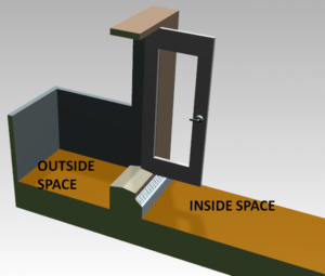
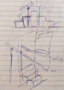
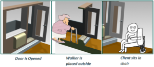
This assistive technology was designed for a quadriplegic individual to permit him/her access to their balcony. The challenge was getting over a high threshold that led to the balcony space as shown in the pictures below. The team consists of one student in mechanical engineer, one student in occupational therapy, and one student in physical therapy at McGill and the client.
The balcony door threshold carried the following dimensions:
- 14” height
- 35’’ doorway width
- 15.5” depth (Figure X).
- 4” heater depth (from wall) - the heater also provided a barrier as it protruded from the wall
- 96.5’’ ceiling to floor height, with a doorway height of 80”
Further, on the outside, the balcony measured 5 feet in width which posed further restrictions on the size of the equipment to be designed.


The client mobilizes using a walker in the apartment and is currently not able to access the balcony. He lives with a spouse but is independent in all activities and wants to be able to access the balcony independently.
Design Challenge
It was not permitted to make any drastic renovations or modifications to the apartment since it is rented and the building manager does not permit the tenants to modify it. Therefore any assistive device must be able to fit in the given space without any major modifications to the space (mounting, etc.). Other major design constraints considered were the following:
- Size
- Storage
- Aesthetics
Earlier Prototypes and considerations
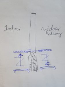
Moving Platform
The device consists of two synchronized platform, one inside the apartment and the other one on the balcony. While the user stands on top of the platform, it will be elevated electrically. A platform will extend out across the doorway to the balcony area to connect to the synchronized platform. The user will walk across the platform, then it will descend through electrical control. This design is discarded due to the large amount of space that it would take up in the living room which was not desirable. There was also a safety concern, as the platform could be unsafe for the user if the elevating system doesn’t function well. If the user falls from the elevated position, it could cause great harm. It would be very hard to store the platforms situated outdoor during the winter time.
Rotating platform
This design consists of one platform rotating up from one side with the user standing on top. The it will click/ connect to the second pole outside. It will rotate down to bring the user to the outdoor area. It does not require the user to walk across the platform, and it takes up less space than moving platform. However the same safety concern applies to the this design, and it holds a higher risk of technical failure. It could cause greater harm if patient falls from an elevated position. The design process of this idea would have to include extensive electrically engineering’s inputs which we don’t have in our team.
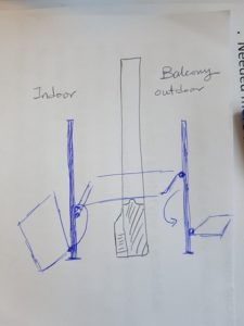
Stairs with rails
This design consists of 3 steps stairs outdoor and indoor, one rail installed on the floor, and one rail attached to the door. As the door is opened, both rails will be rotated to horizontal position and to be locked in this position. The user will push on the rails and steps up and down across the doorway to reach the balcony. The user is able to use maximum 3 steps for stairs when he is healthy and in good state. However, if the user gets sick and have weakness complication, he would not be able to use the stairs. Therefore this design is also discarded.
Final Product
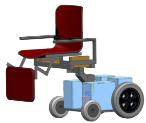
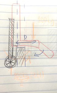
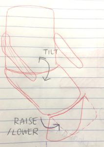
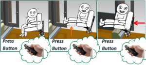
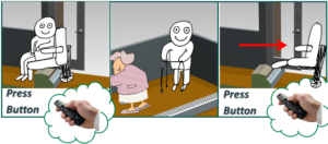
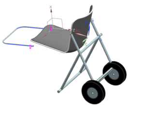
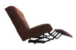
The final design that our team decided to build is a mobilized recliner chair. This technology was meant to allow the client to sit in the chair, lift up the legs by reclining the chair, drive the chair over the balcony threshold, sit back up and get up on the balcony. In order to ensure the threshold is cleared the seat was to be moved forward in relation to the wheels which would support the seat from the rear side. For additional support while transferring in and out of the chair, there would be support on the leg-rest which would come into play while the leg-rest is positioned down.
Proof of concept and Experiments
The initial prototype was conceived through sketches and a storyboard, which explained the operation of the chair. The client was presented with both of these, however this prototype was not completely clear and there was some confusion that remained pertaining as to how the final product will actually work.
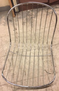
Following that, an initial “proof of concept” prototype was designed and built using a lightweight metal chair. This chair reclined manually and it was not motorized to speed up the manufacturing process. The main purpose of it was to ensure that the chair is safe and stable while the client is seated in it, while it is supported only from the back and to receive feedback on the operation of the chair (such as tilt angle, leg rest angle, etc.).


Review of the design
The final prototype was found to be incompatible with our client’s needs since it did not meet his/her final size requirements. Therefore, the manufacturing process was stopped during Procedure B to save resources. Thus after Procedure B, the rest of the procedure is described in conceptual terms as thought out by the designer. Since this solution may still be a viable design solution for others, we are including these instructions for open use.
List of materials:
| Material | Quantity | Cost and purchase |
| Push-back Reclining Mechanism
(3-way, however a 2-way could be made to work as well) |
1 | https://www.amazon.com/Replacement-Recliner-Mech-Mechanism-Push/dp/B00I82J5SK - (2-way push back) $82.99
https://www.kijiji.ca/ , https://www.varagesale.com/ , https://montreal.craigslist.ca/d/furniture/search/fua?lang=en&cc=us ~$30-$80 (2-way to 3-way push-back recliner chair*) *A full push-back recliner chair was bought for $60, and the reclining mechanism was taken (see Procedure A). |
| Seat | 1 | https://www.kijiji.ca/ , https://www.varagesale.com/ ,
https://montreal.craigslist.ca/d/furniture/search/fua?lang=en&cc=us *Used Seat: $10-$30 Note: Our reclining mechanism came attached to a seat we decided to use |
| Wheel Chair Motor and Controller Assembly | 1 | $75-$300
http://www.ebay.com/bhp/electric-wheelchair-motor NOTE: We used an old donated wheelchair |
| Wood Planks | 4” (width) x 1.5” (thickness) x 40” (length)* | ~ $ 8.00 + Shipping https://www.mcmaster.com/#wood-screws/=1cdutvd |
| Wood Screws | 4 | ~$8.00 + Shipping
https://www.mcmaster.com/#wood-screws/=1cdutu3 |
| Rectangluar Steel Tube | 1” OD, 6 ft* | $22.00 + Shipping
https://www.mcmaster.com/#rectangular-tubing/=1cduv6n Or local metal suppliers |
| Rectangular Steel Bar | 3/16” T, 3” x 3” | $9.22 + Shipping
https://www.mcmaster.com/#1388k662/=1cdutbn Or local metal suppliers |
| Bolts | ¼-20 x 2 | $7.50 + Shipping |
*includes spare material
Required Tools:
- Safety Glasses
- Scissors
- Screw Driver (head will depend on the type of seat/reclining mechanism purchased)
- Ratchet Set
- Angle Grinder with Metal Cutting Wheel
- Hack Saw
- Drill
- File
- TIG Welder and appropriate Welding Equipment (Steel welding)
Procedure
The procedure is split into 3 parts (part A, part B, and part C). Depending on if you purchased the materials directly or are taking the parts from already-built assembly’s or second-hand parts. If the materials are bought directly you may skip Procedures A (recliner disassembly) and/or B (powertrain disassemby from an electrical wheelchair) and move on to the final procedure C. Procedure C details the final assembly of the reclining mechanism, seat, motor assembly and the building of the new base.
PROCEDURE A - Recliner Disassembling
**Skip this step if you have bought the sole reclining mechanism (see link 1 in the material list table for push-back reclining mechanism).
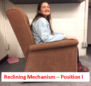
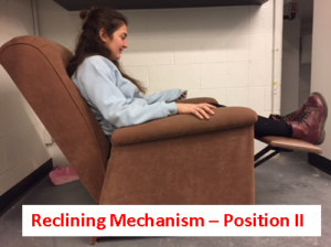
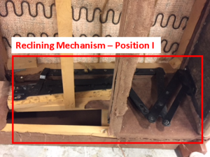
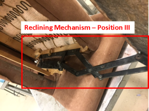
DISCLAIMER: This procedure details disassembling a full recliner chair that was bought off Kajiji to obtain the reclining mechanism. Since these chairs will be bought second-hand, each recliner may have a different structure and may require a different disassembling procedure. This procedure will show step-by-step how to disassemble the chair that we obtained for this project and can be used as guidelines. To ensure the correct re-assembly of the reclining mechanism, be sure to take many pictures and document each step of the chair disassembly. The photos below are the Recliner Chair in 3 positions. Position 3 is the pushed-back position.

STEPS:
1/ Cut off Upholstery to view structure of chair. The below figure shows the upholstery cut off and the wooden base of the chair is shown.
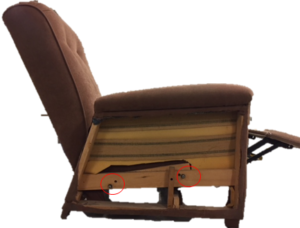
2/ Turn chair on its side to see underside of chair and reclining mechanism. Pictures below show the underside of the chair with the reclining mechanism in the extreme positions. In position 2, the reclining mechanism is mounted to the seat and the base through wooden screws which are then bolted to the (wooden) base of the seat and the wooden support.
3/ Use a socket head and ratchet and take out the bolts/screws that hold the reclining mechanism to the base. Keep these as they may come in handy for the reassembly of the reclining mechanism to the base. The location of these bolts on our chair are located in figure below:

4/ Take the seat+Reclining mechanism apart from the seat base.
5/ If you wish to re-use the seat, you are finished at this step. However, if you wish to replace the seat and ONLY use the reclining mechanism, use a socket head/ratchet to remove the bolts/screws attaching the reclining mechanism to the seat. Now you should have a fully disassembled seat!
PROCEDURE B - Powertrain Disassembling from Electrical Wheelchair
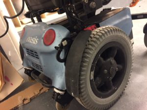
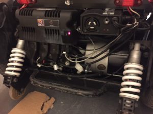
This procedure describes the process of disassembling the powertrain from an electric wheelchair. This is in the case that you have either bought an electric wheelchair or are taking apart an old wheelchair. This procedure is to be skipped if the motors/shafts/wheels were bought separately. The figure below is the motor assembly of an Electric Wheelchair with casing on.
1/ Read the user manual of your wheelchair! This step is critical in understanding the proper safety measures for disassembly. Further, it is recommended to document the disassembly process (with pictures) as this can help for reassembly. The manual for the electric wheelchair used for this project is the following:
http://www.orthofab.com/wp-content/uploads/2015/12/User-manual-OASIS.pdf
Ensure that the chair is powered off when moving to the following steps.
2/ Use a screwdriver or ratchet set to remove bolts holding the rear casing (rear casing covers the motor assembly).
3/ Remove rear casing (pictured below).
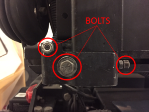
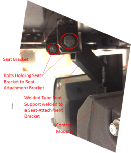
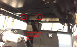
4/ Using a ratchet set, take apart the upper parts of the seat frame that hold the seat onto the base of the chair. If the tubes are welded, use an angle grinder to cut the tubes off*. For the particular chair we were working with, the entire seat was bolted on via various metal brackets on the chair. The placement of these bolts are shown in the pictures below.
Note: if using an angle grinder, use property safety equipment such as safety glasses. If the same control interface is desired for the final prototype, protect all wiring from damage in all the cutting steps.
5/ Once the bolts are removed (or the necessary tubes are cut), remove the seat and attached frame seat support.
PROCEDURE C - Final Chair Building & Assembly
This procedure details the final assembly of the chair. If the reclining mechanism and electric powertrain were bought separately, you can skip directly to this procedure. Since the prototype was not built for the client, this procedure is in the conceptual phase as thought out by the designer. It is recommended to wear safety glasses throughout the entire assembly.
PROCEDURE C-1: BUILDING OF CHAIR BASE
1/ Using a hacksaw, cut the rectangular Steel tube in 2 pieces of 24” and 2 pieces of 10”.
2/ File the ends of all of the cut steel tubes such that they are perpendicular edges.
3/ Jig one of the 24” long tubes in between and perpendicular to the two 10” tubes, placed 0.5” from one end of the 10” tubes.
4/ Ensure a good fit, clamp and clean the tubes, proceed to weld these tubes.
5/ To create Steel brackets that will be welded to these tubes, in the 3/16” thick Steel plate, use a center punch hole, 0.75” from one edge of the sheet, and 2” from the other edge. Drill a ¼” Hole.
6/ From the same edges, mark out.
7/ Using a hacksaw, cut the 4” x 1.5” planks of wood to the following dimensions and quantities in 2 pieces of 18” length.
8/ On the 17” long pieces, mark out drill holes using a marker or sharpie centered in the width of the plank and 3” from each end of the plank. Drill Pilot holes at these marks. It is important that the distance of the holes from the edges are identical on each plank of wood.
9/ Align the 17”.
PROCEDURE C-2: FINAL CHAIR ASSEMBLY
1/ Using Wooden screws, screw the base of the reclining mechanism to the Chair base.
2/ Once attached, attache the chair base to the electric powertrain at two mounting points in the center through 2 ¼-20 bolts as shown in the Figure.
3/ Place arm rests around chair and ensure that all wiring is secured properly.