The Design of an Auditory Feedback System for a Washing Machine
The addition of hardware to the existing user interface of a washing machine, allowing for auditory feedback.
Problem:
Kim Holdbrook is a licensed massage therapist living in Montreal. She lives with idiopathic optic neuritis which caused her to lose complete vision in both eyes by her early thirties. Through adapting to this new lifestyle, Kim has since become the owner of her own business: Hands That See massage studio. Here, she manages a team of employees and that assist her with her often-booked weeks.
Kim’s business is at a separate location from her home, and she will regularly find herself transporting loads of bed sheets to and from her studio at the beginning and end of most days. As a result, she is consistently using her washing machine at home and considers it to be her most used appliance.
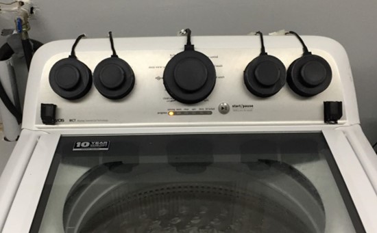
The main problem with Kim’s machine is that there is insufficient user feedback for visually impaired users, deeming it to be fairly inaccessible. The machine’s off-the-shelf interface consists of 5 rotary knobs, allowing the user to choose the different settings that are printed onto the machine’s face. These settings include water temperature, load size, wash cycle, and more. As a result, there is a lack of communication between the machine and the user, causing Kim to be unable to use the machine to its fullest extent. She expressed to our group that she wants to be able take advantage of all of the different settings that are allowed by the machine, rather than being forced to use the same pre-set wash cycle for all different types of loads.
Kim presented us with the challenge of creating an assistive technology that gives her machine the ability to “talk.” She believed that this technology would provide her with more productive interactions with the machine by giving her the choice of which cycle to use on different types of laundry.
Prototypes and Experiments:
The first approach made was through the use of a "simulation" prototype. The goal of this was to achieve a better understanding of how a potential solution involving auditory feedback might work. The video below shows a simple example of how an interaction including feedback for the user could work.
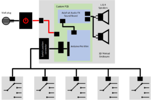
Through working through some of the logistics with Kim, such as discussing our timeline and budget and determining the extent to which our solution would be "permanent," we settled on the solution of adding an external interface to her machine to work with it’s current interface while maintaining an as-close-as-possible user experience with the machine. Essentially, the plan was to add our own knobs onto of the machine’s knobs to work just as they normally would, but the new knobs and other added hardware would allow for there to be outputted audio feedback with each rotation of a knob. A high-level layout of this design was drawn using Visio to get a better idea of how everything would come together:
This project was split into three main categories: electrical design, mechanical design and software design. Each of these designs played a crucial role in getting a fluidly functional technology by the expected delivery at the end of April. Given that the project’s design timeline began in January, it was necessary to develop these designs in parallel. This was initially split between simultaneously developing an electrical/software design on a prototyping platform, while designing the mechanical structures through a modeled recreation of the washing machine using a CAD tool. To begin, an overview of the each design's responsibilities, challenges and constraints were drafted:
The electrical design had the following responsibilities:
- Translating the user’s input into some sort of data the software can make use of
- Outputting the fedback audio
The main challenge of this design was:
- Conducting the data acquisition of the user input
The main constraints presented were:
- Limited amount of digital inputs
- Rotating knobs were the source of user input
The mechanical design had the following responsibilities:
- Package the electronics soundly and sleekly for a minimal hardware addition to the machine
- Withstand repeated use and possible accidental bumps
The main challenges of this design were:
- Reliably housing sensors conducting the data acquisition to consistently work
- Maintain tight tolerances as required by sensors
- Ensure that the hardware does not interfere with regular use and that the knobs ergonomically comfortable.
The main constraints presented were:
- Limited amount of machine face surface area to work with
- The design must be removable in the case it is no longer wanted
The software design had the following responsibilities:
- Interpret the electrical inputs as the machine's current "state"
- Conduct communication to trigger the audio without error or excessive latency
The main challenges of this design were:
- Writing an algorithm that can interpret any combination of user-inputted settings
- Ensuring the system can self-recover if the user-input is not deemed as valid
The main constraint presented was:
- Testing an algorithm without a debugger and relying on print statements
Electrical:
The first task in this project was deciding the method in which the knobs position would be interpreted. The real challenge was finding a way to interpret a turning knob into a signal that could then be used. The difficulty here is making use of the position of the rotating knob relative to the stationary face of the machine. A few options were explored, such as using an angular position sensor on each knob, or through having some sort of conductive contact between the rotating knob and the face of the machine. The disadvantage to the sensor is that some sort of wired signal would have to exist on the rotating knob, which could potentially get caught mid-rotation or get accidentally yanked. The disadvantage to the conductive contact is the positional tolerancing that would be required to ensure a proper contact is maintained. Ultimately, it was decided to use magnetic reed switches as the method of position sensing. The reed switch solution is a two-part mechanism; the first piece is a magnetic actuator, while the second is a switch that opens or closes depending on the proximity of the magnetic actuator. In the application of the washing machine, an actuator would be place within each knob, while a switch is placed at every machine setting. The advantage of this solution is that there are no wires originating on the rotating knobs, and there is a distance tolerance high enough to allow for the inevitable mechanical design/assembly errors.
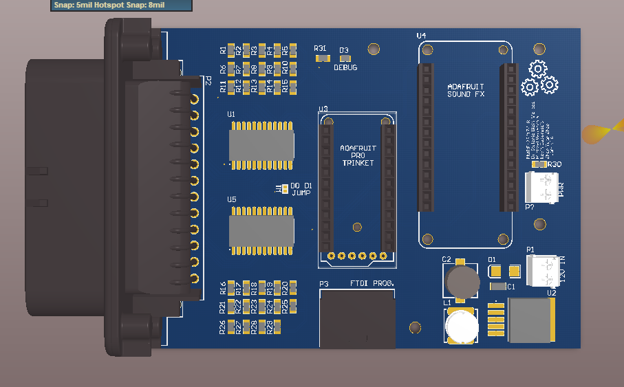
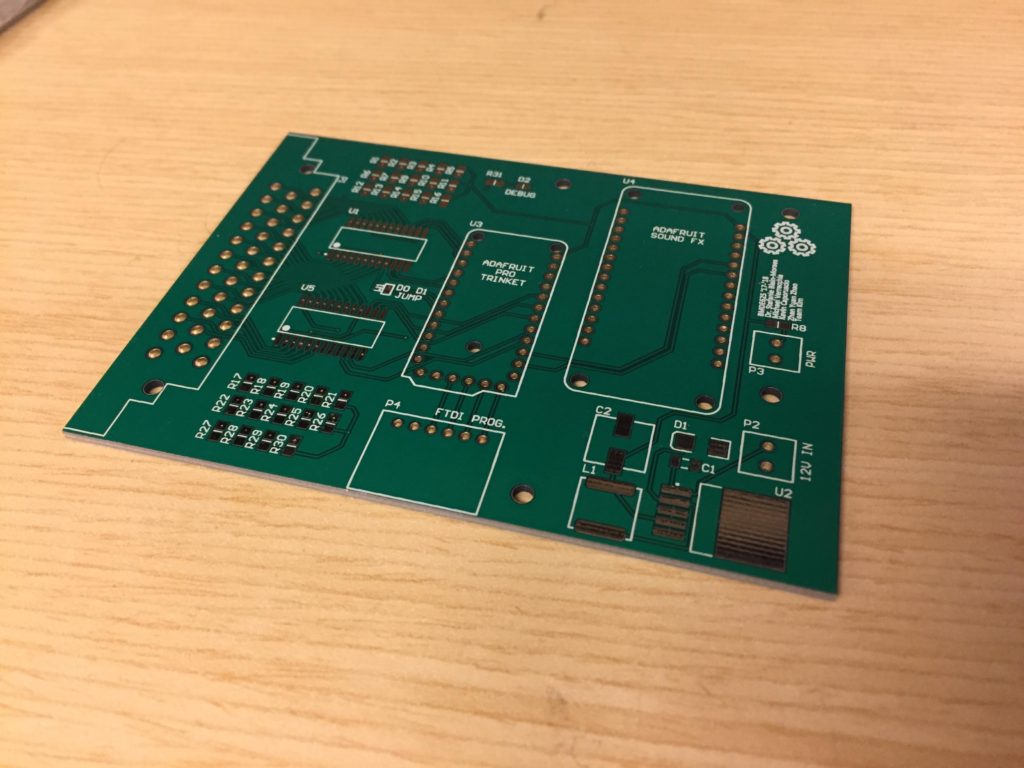
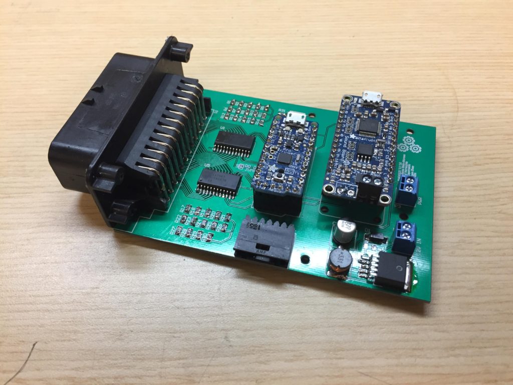
Once this decision was finalized, it was required to multiplex the 24 different sensor readings as active-low digital inputs into a microcontroller. The microcontroller chosen was the Adafruit Pro Trinket due to its small size and compatibility with the Arduino IDE. The device that would be responsible for the audio output was the Adafruit SoundFX board, which was chosen for its ease of implementation within the Arduino environment. A schematic of the full circuit can be found below:
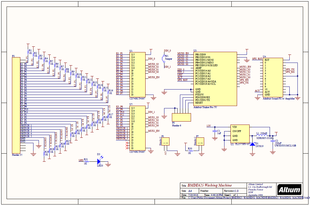
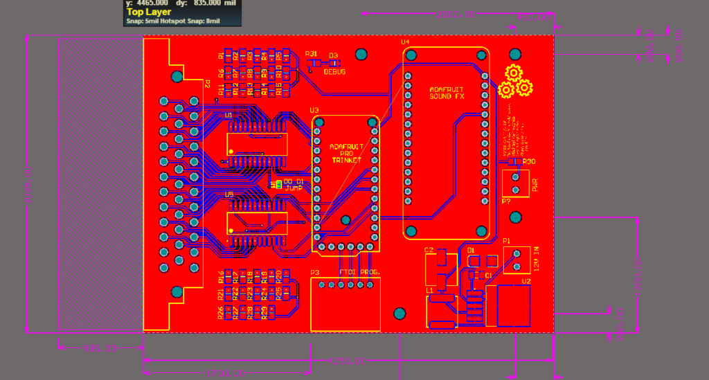
This circuit was first implemented on a breadboard to prove its functionality as designed. Once this proof of concept was confirmed, a proper PCB was designed, ordered and manufactured.
Mechanical:
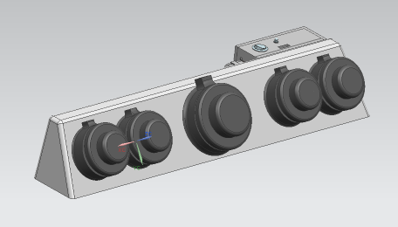
The first task in the mechanical design was to take proper measurements of the machine to recreate interface in a CAD environment. This allowed for multiple design iterations to be made without having to 3D print the hardware. Additionally, tight tolerancing could be met due to the highly accurate representation of the machine that was made. The model resulted as the following:

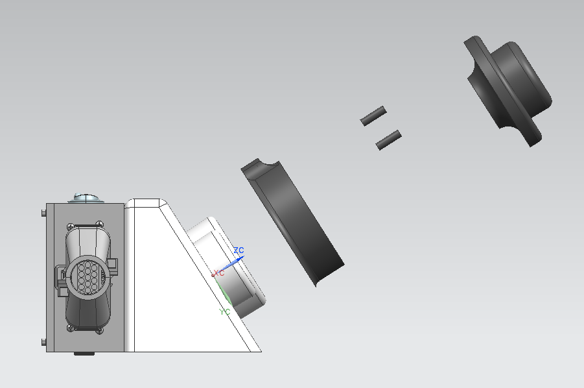
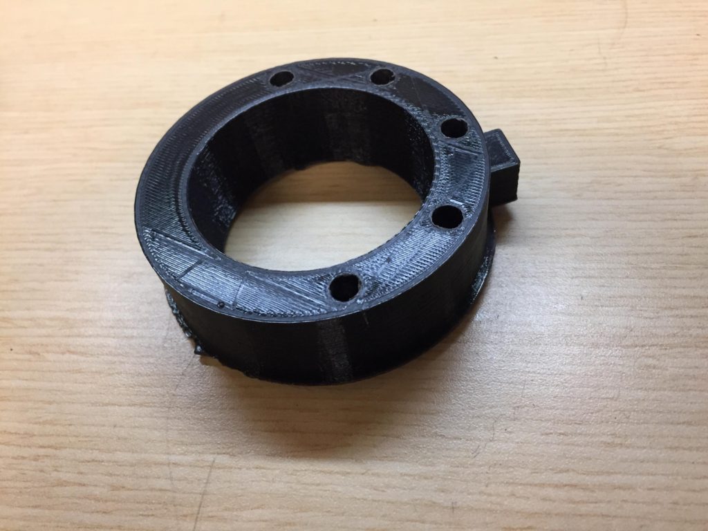
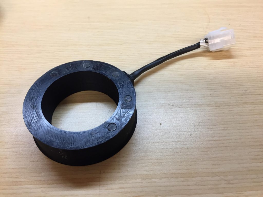
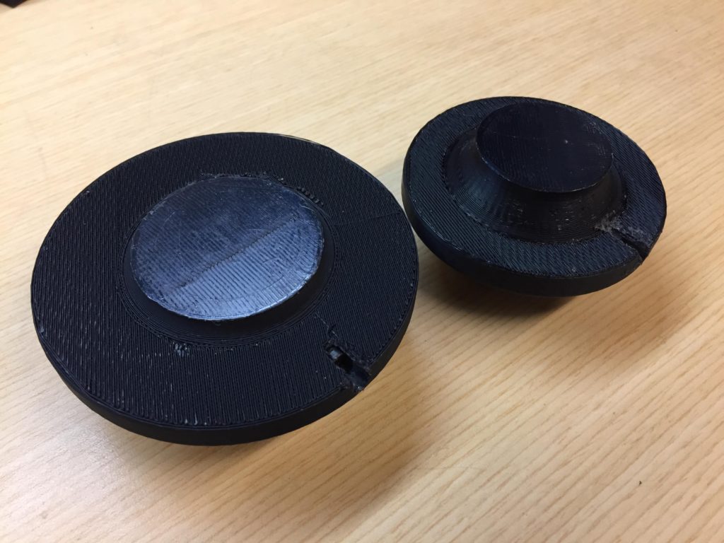
The added parts to be placed on and around the rotating knobs were to look as follows:
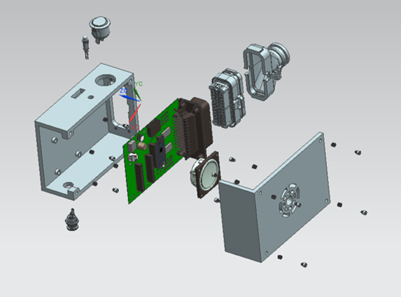
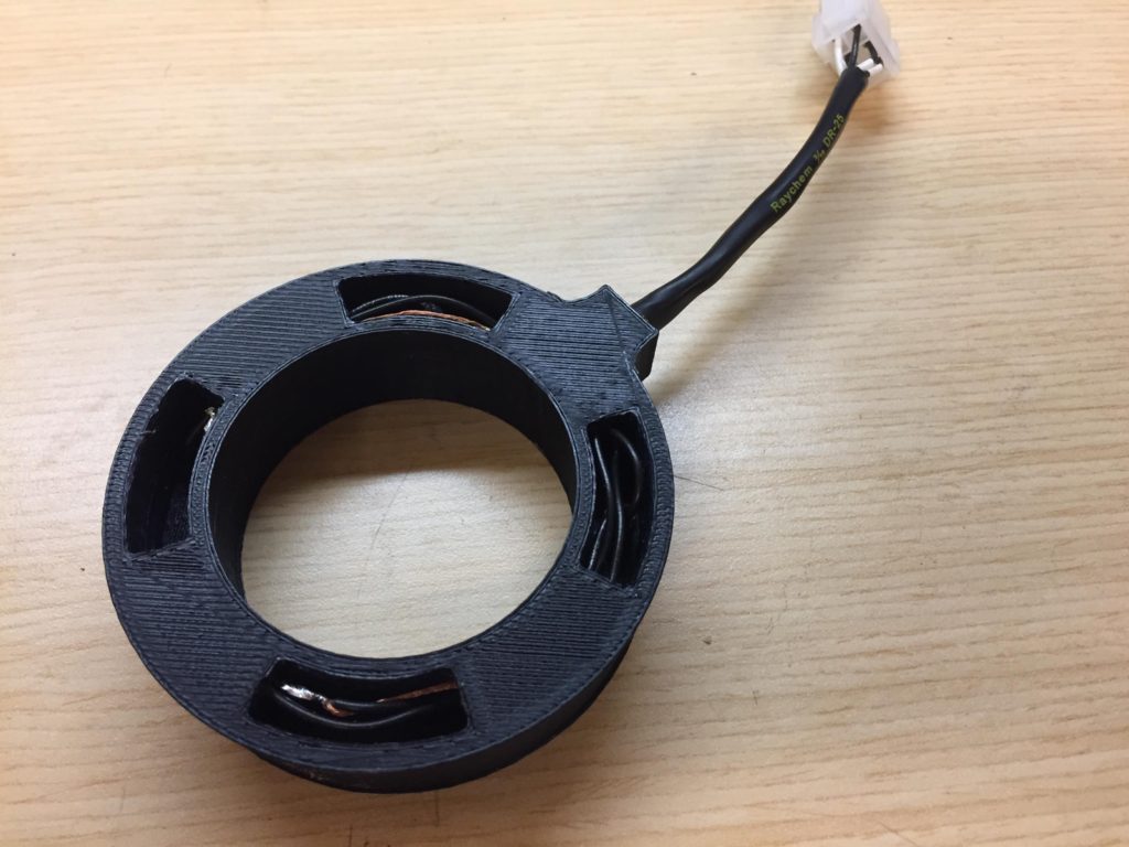
The annular piece that sits stationary around each knob is what holds the magnetic reed switch, while the rotating piece that sits on top of the knob holds the magnetic reed actuator. Additionally, the rotating piece was designed to recreate the exact shape and dimensions of the knob it is sitting on. Side exploded and cut views of the design are more clear here:
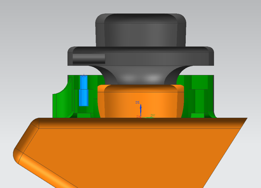
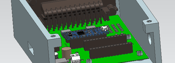
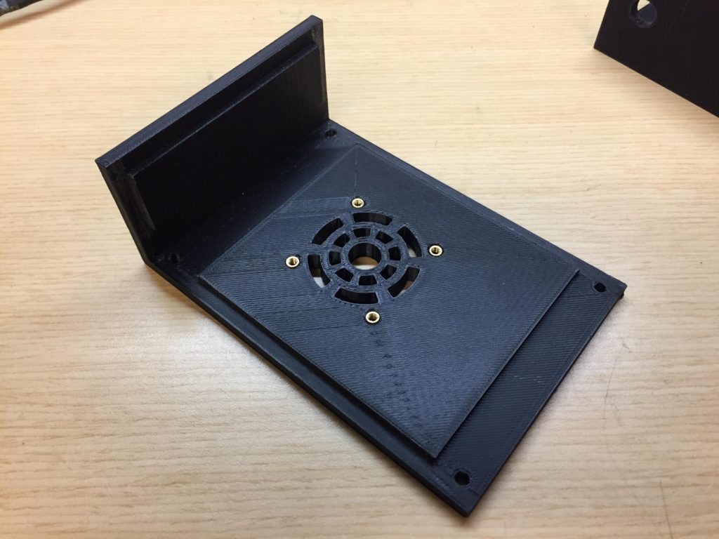
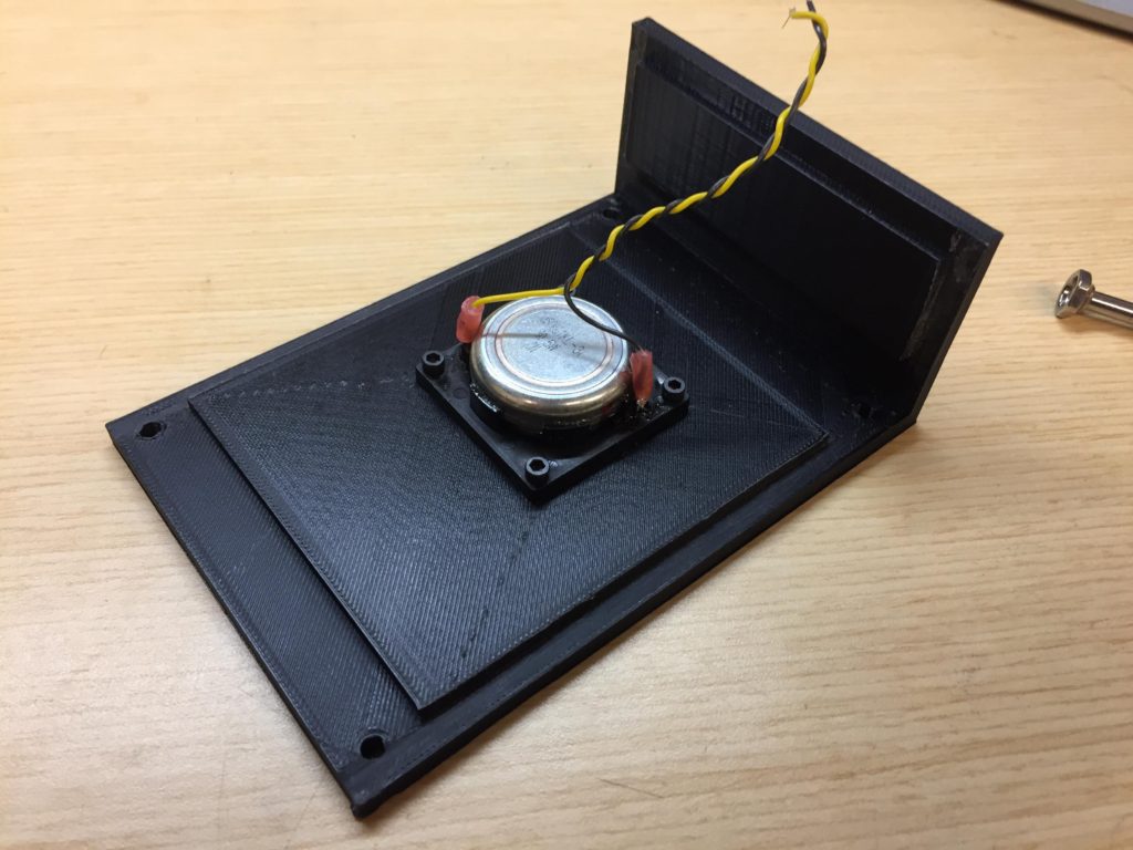
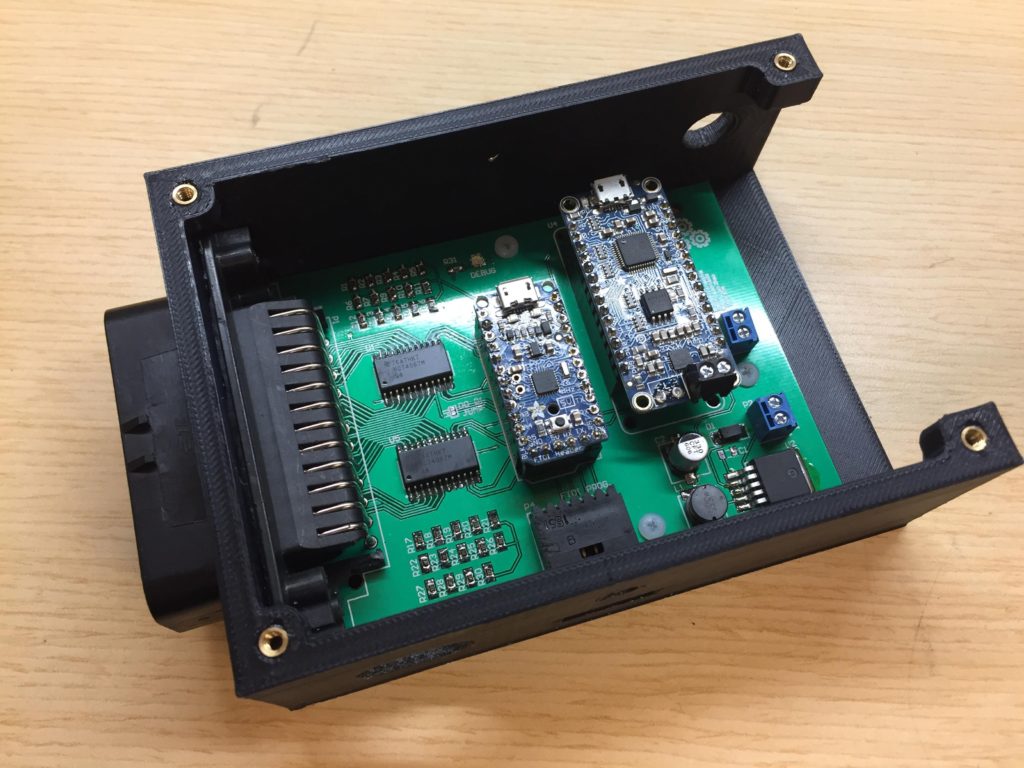
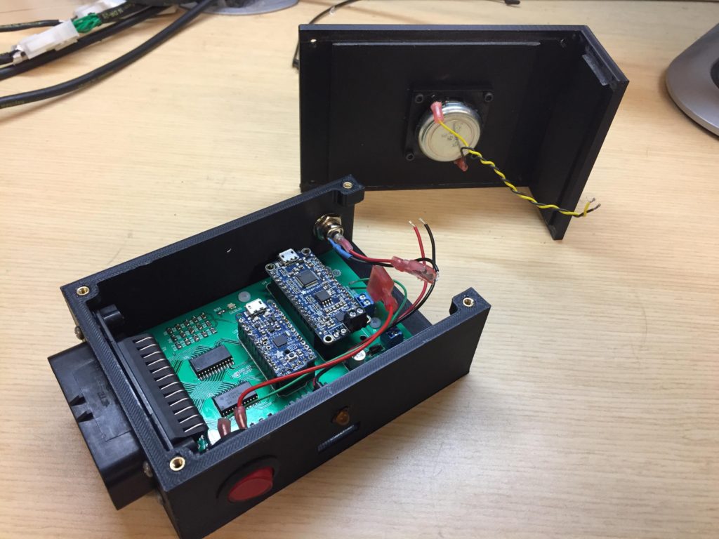
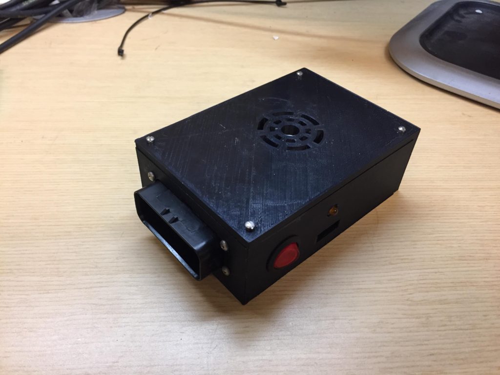
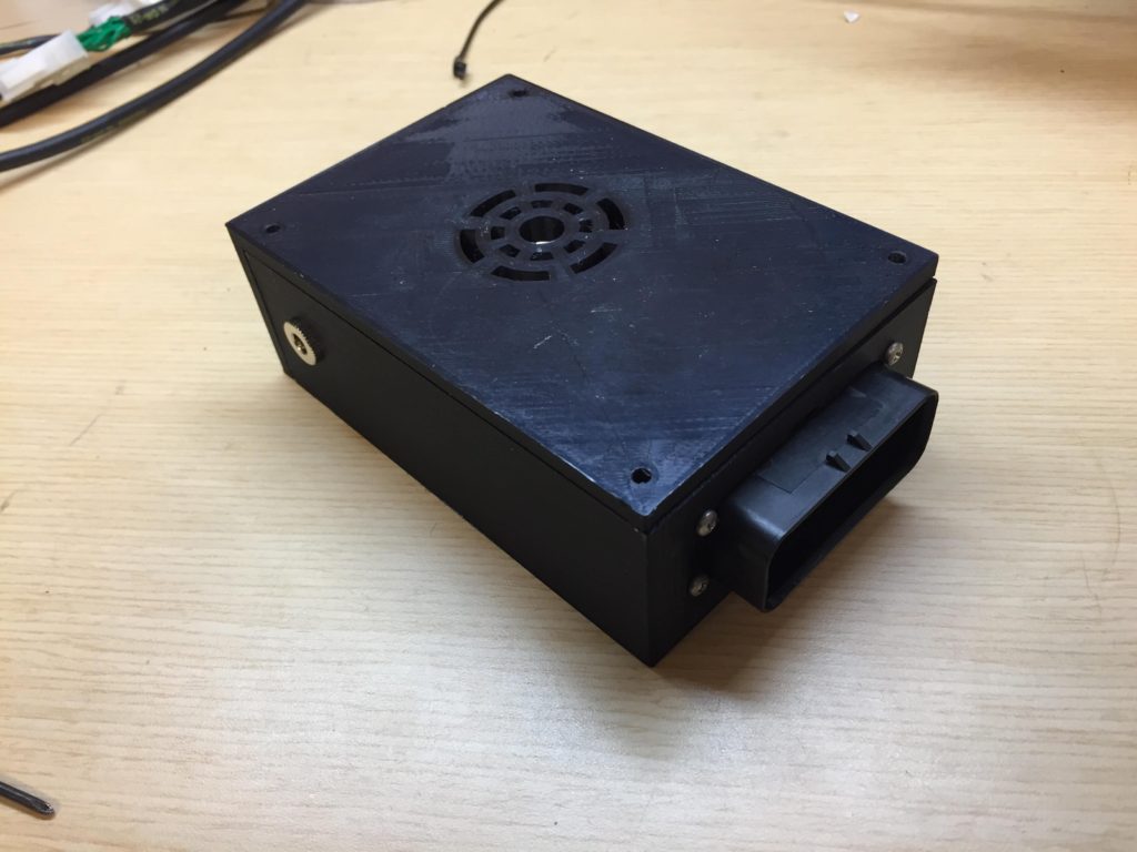
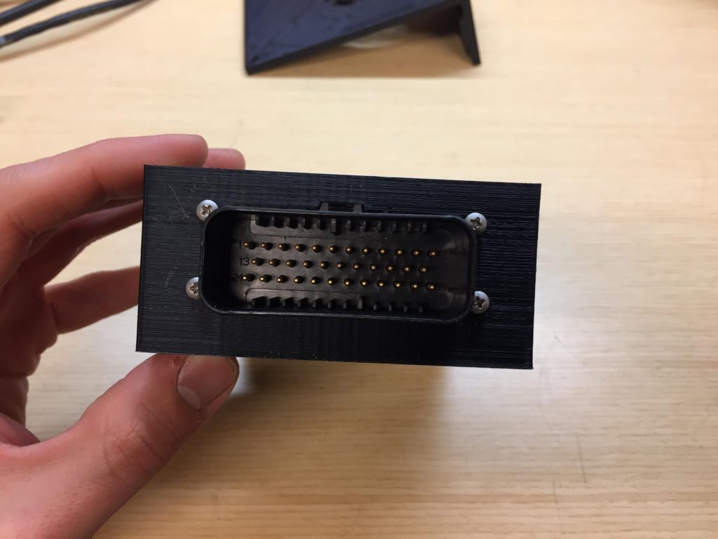
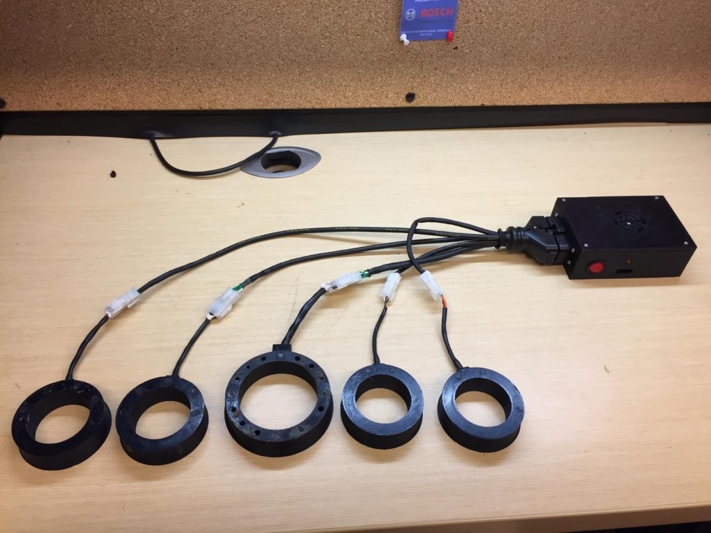
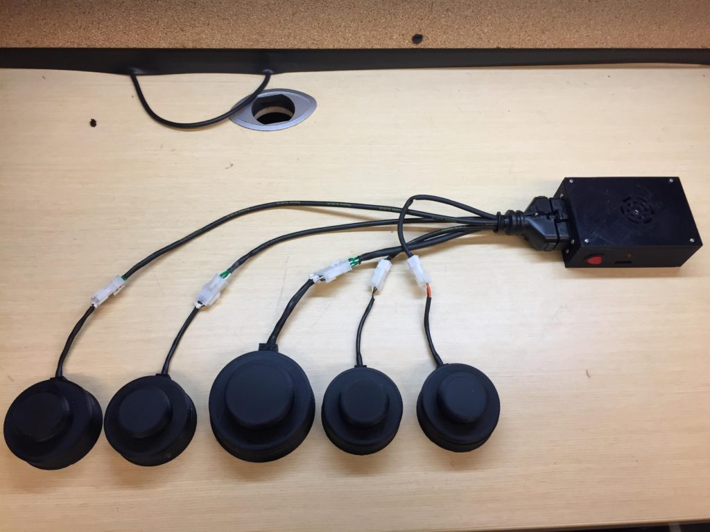
Each annular piece has a small bundle of wires that come out, returning the signal positions to the microcontroller. A small enclosure was made for the manufactured PCB, of which also housed the speaker, the power-jack input, the on/off button, and the connector for all the signals. A breakdown of the enclosure design is more clear here:


Software:
The main algorithm run on the Arduino works as follows:
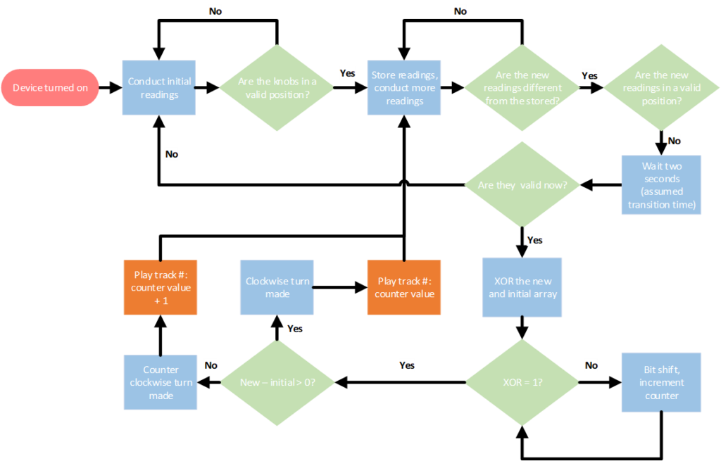
The key in this algorithm working is the program’s ability to validate the knob’s positions, and then successfully interpret an intended change in setting. This is easily accomplished through the use of a waiting period and bit comparisons. The main assumptions of this algorithm is that it takes at most 2 seconds to change settings, only 1 setting is changed at a time, and that 5 valid knob positions must be present in order for the algorithm to initially proceed. As a result, the program can pinpoint to exactly which position a setting was just changed to.
Final Solution:
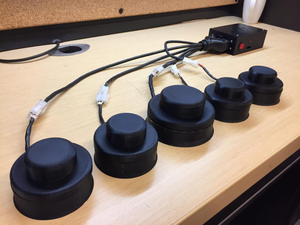
The final, installed product appears as follows:
Through the successful integration of electrical, mechanical and software systems, the interface can properly interpret the most recent setting changed to by the user and provide audio output of that exact setting. Additionally, the interface can be left on due to its overall low power consumption and its ability to auto-recover from any positional error once corrected.
Fabrication/Installation/Usage Instructions:


Required Materials:
Helpful Contacts: