The challenge:
The device our team created was designed for and with a client named Ron. Ron has Retinitis Pigmentosa, rendering him legally blind. He is retired, but actively engages in his community, through sports, travelling, and volunteering.
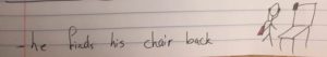
Ron expressed that one of his major frustrations and challenges was not being able to locate things independently in various environments, so he asked us to work with him to build a tracking device. Ron enjoys traveling, but some things such as; finding his suitcase on the carousel, or finding his seat again after getting up to go to the bathroom, or finding the door to his hotel room are difficult to do independently.
Ron has tried many of the tracking devices that exist on the market today, such as the iHere and the TrackeR. However, none of them met his specific needs. For example, they were not loud enough, did not have rechargeable batteries, used a monotone pitch, did not connect to his phone, and/or could not be used by other users at the same time.
Thus, our objective was clear: to create a versatile tracking device that was loud enough to be useful in a noisy environment in addition to being portable and accessible by multiple users. We also needed to design a compatible, user-friendly iPhone App which could be used to control the device.
Prototypes and Experiments:
Throughout our design process, many prototypes and experiments were completed. Fortunately, Ron had a very specific vision of what this device would be like, thus making our design decisions simpler. The following are some of the ideas we presented to Ron, in the initial stages of the design process.
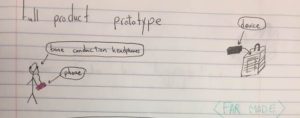
Design #1:
This first design idea was one that involved a sticker that Ron would stick onto the item or area that he wanted to find.
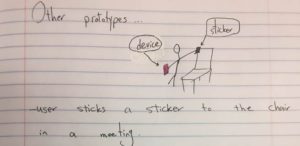
When trying to locate the item, Ron would use a headset which would 3D locate the item and modulate the sound heard depending on the 3D position of the sticker in relation to the user.
This would allow him to be able to track the device using sound coming from his phone and not the device. It would also necessitate the use of a headphone every time Ron wanted to locate the sticker.
Ron’s Reaction: Ron wanted a sound to come from the device. He voiced that the headphones could be useful in certain environments (e.g. when he wanted to be discreet with his sound). He also said that he did not mind if the tracker was bigger as long as it had a good speaker, as he would most likely use it during situations that would not require an item as slim and discreet as a sticker (e.g. in a backpack or luggage bag, in a hotel room etc.).
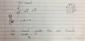
Design #2:
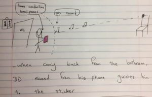
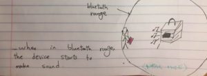
This second design was made taking into account the feedback received after the first iteration of the tracker. We wanted to include the headphone element that Ron seemed to like, while still having sound come from the device. Thus, in this prototype, the tracker is no longer a sticker but a physical device that Ron can place where he wants. It works by playing 3D sound through his headphone when outside of the Bluetooth range, giving Ron an idea of which direction to head in.
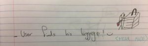
Once inside the Bluetooth range, the device itself will start playing a sound. At this point, Ron can take his headphones off and listen for the sound himself to find the device.
Ron’s Reaction: Ron said that he likely would not use the far-mode 3D sound tracking tool, as most things that he looks for are within the Bluetooth range. He thus did not feel like the far mode would be particularly useful to him. He did, however, like the use of a device and his phone that made sound and the idea that the phone would trigger the sound within Bluetooth range.
Design #3:
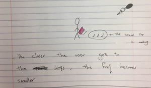
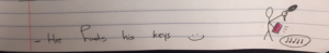
This design idea features the phone making sounds to track the device. The idea is that the phone would ‘beep’ faster the closer it got to the device. It would work within Bluetooth range. This design feature would allow the user to discreetly use the tracking device without the device making a loud sound that might disturb those around.
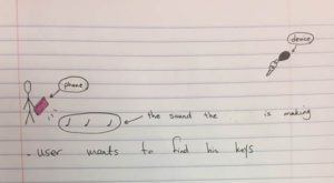
Ron’s Reaction: Ron said that it would be hard to figure out where the item or area being located really is as the beeps are all relative and he might not know what a fast beep is vs. a slow beep. He also said that he preferred the sound coming from the device if he had to choose between a sound from the device vs a sound from the phone. However, he appreciated the idea of using an app to connect to the device.
Other Decisions:
The Sound:
We had originally picked out 12 different ringer sounds with fluctuating pitches to show to Ron. The idea was for him to choose out only one sound that he liked. While talking to Ron, he noted that not one sound seemed to cover all situations he would be using the tracker in.
The App:
The App we had in mind was one that used a touch interface in order to control its functions. There were 7 buttons in the current order: name, refresh, sound increase, track change, sound decrease, find, and mute. The find button was placed at the end of the menu options as it was a made a bigger icon that Ron could 'feel'. When Ron first used this, he used VoiceOver (not the touch interface) and felt that the label order was not efficient.
The Buttons:
The buttons on the device were placed in the following order (from top to bottom, left to right): Volume increase, volume decrease, power, mute, and track change. Ron found it hard to find the mute button, because it was not along the edge of the box. As an afterthought, he wondered whether the mute button was necessary if he had a power button. The power button was found to be hard to use because it did not have a sound indicator of when it was on or not.
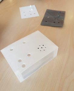
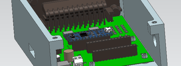
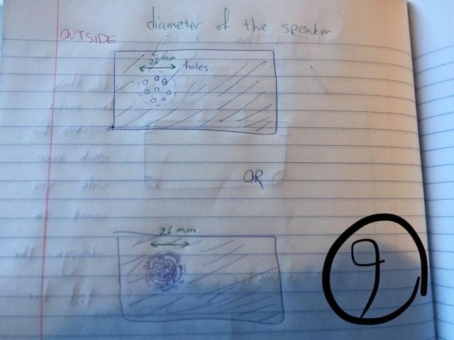
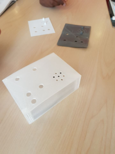
This photo shows some of the first 3D printing prototypes with the original spacing for the holes.
The Shape of the Box:
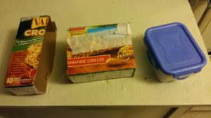
These boxes were for Ron to feel, in order to determine a satisfactory size and shape for the device.
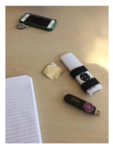
Here we used remotes to represent the device and a plastic sheet to represent the sticker for demonstrating Prototype 1.
Our next challenge involved designing a sturdy and ergonomically-viable outer casing to house the electronic components of our device. Fortunately, McGill library services allow students access to a variety of 3D printers; a service which is covered by tuition fees with no additional charge. This has allowed our team to minimize the associated expenses involved with utilizing pay per use machines.
Prototype Specifications/Conceptual Design: The drawings below illustrate the preliminary phases, all of which address the individual components of the outer casing that must be accounted for in the final product.
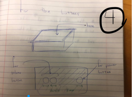
All of the above components were later integrated into a single casing, both practicality and maximal protection of the inner electrical components taken into consideration.
Software: Though there is a variety of software programs available, our team chose to use Onshape computer-aided design software (CAD). This state-of-the art program is delivered over the Internet using a Software as a Service (SAAS) model, making utilizing cloud computing, and allowing users to interact with the system via a compatible web browser or Android applications.
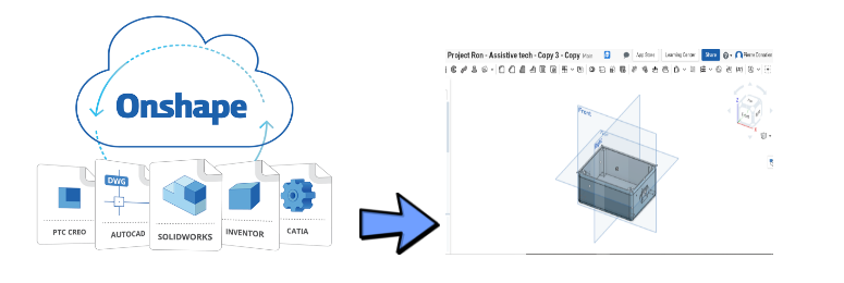
The advantage of this program is that it allowed us to collaborate on a single shared design, allowing for all team members to have equal access to a single project, which improved team efficiency and collaboration.
Executing the Print: This was final phase of this process involved 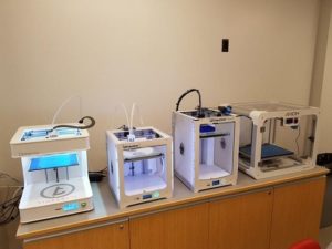 selecting the right printer. McGill 3d printing labs offers 4 different models of printers (Tinkerine Ditto Pro, Ultimaker 2 Extended, Ultimaker 3, Airwolf Axiom), all of which have different design features and printing quality. We were unsure which of these printers were ideal for our product.
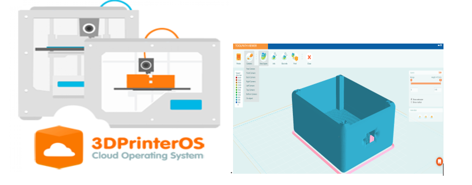
i) Interfacing with the Printing Lab: Our team was able to interface with each printer via an online platform known as 3dPrinterOS; a service which allows companies and schools remote access to connected 3d printers. This was extremely convenient and aided greatly in meeting our internal deadline.
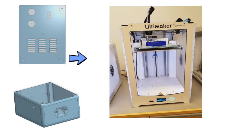
ii) Finalizing our Print: The final step involved selecting the ideal printer to create our finished product. We had attempted to print multiple designs variants with multiple printers.
Both our team and client had come to the consensus that the print created using the Ultimaker 2 Extended was the most successful. Therefore, we had chosen this printer (below) to craft our finished product
Success Metrics:
Through our prototyping and experiments, we determined many success metrics; in other words, the minimum viable product that Ron would be satisfied with.
Receiver: Standalone Device. 5 cm (height) x 4cm (width) x 2.5cm (depth)
Size and Shape: Rectangular, small enough to fit into pocket Buttons: i) On/Off switch ii) Volume control (device/app), 2 buttons, high/low continuum Sound: low and high ranges of sound, varies in pitch. Volume to go up to 90 dB at 10m Battery: Rechargeable with up to 4 days duration. Multiple Users: should have access App: Uses Voiceover for button recognition Range: Minimum - Bluetooth range (75-100 feet)
The Final Product:
The final SeeBox, is a 10.7 (L) x 8.4 (W) x 4.7 (D) cm rectangular box. It is a simple box that consists of a speaker, 2 volume buttons, a power switch, a latch, and a microUSB port for charging. This device can be connected to the SeeBox app via Bluetooth which has been configured to be compatible with VoiceOver, which suits the needs of the user. Through the app, the user is able to control the device (i.e., change the volume, change the track, mute the sound etc.).
The device is intended to be left in a specific location of the user's choice. Activating the App will cause the device to make a sound so that its location can then be found. There are two different sounds that can be played by the device and each of their volumes can be customizable through the App or the device. The two sounds allow the user to use the device in both quieter and louder environments.
The furthest distance between the phone and the device at which the device can still be activated is approximately 70m. The volume goes up to 70 dB at a distance of 10m. The battery lasts for 4 days.
How to create the SeeBox:
The following are step by step instructions that outline how to create the SeeBox. It is important to note that these steps do not need to be followed in this specific order, as it will depend on what is convenient for you. Also, as McGill students, we had access to free 3D printing services; this may require extra fees outside of the education setting.
The following is a list of the materials and tools we used. Please note that products could vary based on your design preferences and budget.
Materials:
| Item/Material | Purchased from/Vendor | Cost estimate
*Will vary in price |
|
AUKEY Portable Bluetooth Speaker with Power Bank Function for iPhone, Samsung Phones, and More |
Amazon | $40.00 |
| Breakout LE BT BLE 4.0 NRF8001 V1 | https://www.adafruit.com/product/1697 | $20.00 |
| FX Sound Board Wav/OGG | https://www.adafruit.com/product/2133 | $20.00 |
|
Adafruit Pro Trinket - 5V 16MHz |
https://www.adafruit.com/product/2000 | $10.00 |
| PCB | Labo Circuits | $260.00 |
| Smartphone | Provided by Client | N/A |
| Case | 3D Printed | < $20.00 * |
| AC/DC Wall Mount Adapter 5V 10W | DigiKey | $12.00 |
Tools and Machines:
- Soldering tool
- 3D printer (Ultimaker 2 Extended)
- Super Glue
- Foam
Helpful Contacts and Resources:
Digikey: https://www.digikey.ca/
Labo Circuits: http://golabo.com/
McGill 3D Printing Service: https://www.mcgill.ca/library/branches/research-commons/3d-printing
Step by Step Instructions:
The following are step by step instructions that outline how to create this product. It is important to note that steps do not need to be followed in a specific order, as it will depend on what is convenient for you. The lists of materials and tools used are also provided.
This can be considered a resonate design, as it can also help sighted people find items or places when their cognitive or sight faculties are otherwise preoccupied. It may also allow an easier access to personal items when traveling. For example, instead of needing to concentrate on finding a piece of luggage on the carousel, the user can simply activate the SeeBox to determine exactly when it arrives on the carousel, minimizing the need for attention on the luggage coming out. This can be useful for parents, those who are busy and need to multitask, those who are preoccupied with other things while traveling etc. It can also be used for sighted populations that may need auditory cues. For example, someone who may have a decreased attention span or a someone who has difficulty with visual recognition of their object amongst similarly designed objects may find this device useful.
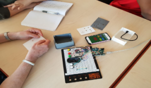
Step 1: Building up the Circuit
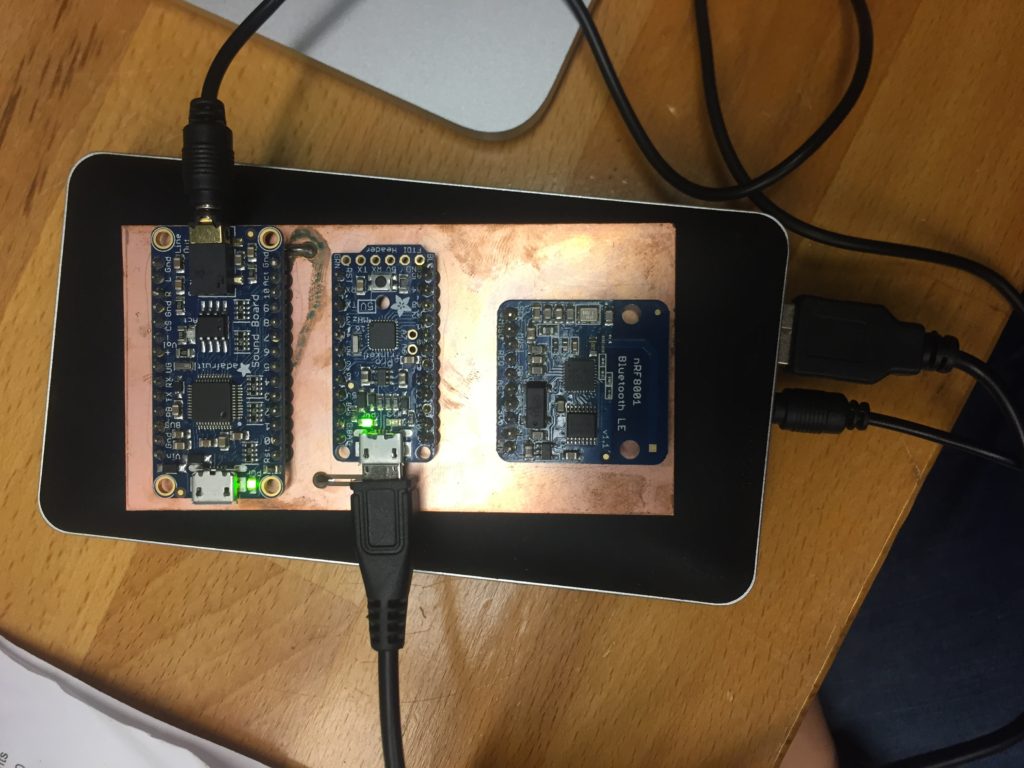
Using these three components from Adafruit, and combining the connections, we built a Bluetooth and sound functionality on the circuit.
Processor:
Adafruit Pro Trinket - 5V 16MHz as the microprocessor
https://www.adafruit.com/product/2000
Soundboard:
Adafruit Audio FX Sound Board - WAV/OGG Trigger with 2MB Flash for controlling the sound.
https://www.adafruit.com/product/2133
Bluetooth Module:
Bluetooth Low Energy (BLE 4.0) - nRF8001 Breakout - v1.0 for the Bluetooth connection
https://www.adafruit.com/product/1697
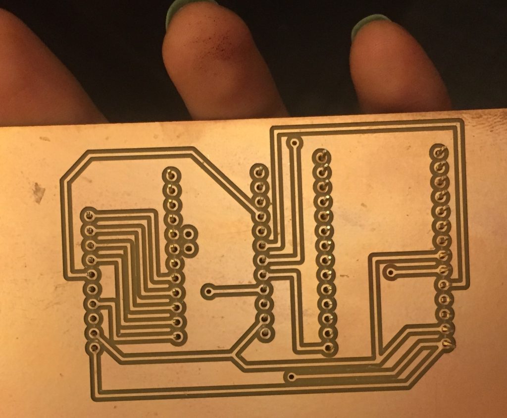
In order to combine the connections and build a compact circuit will all three modules working together, you would generate and manufacture a Printed Circuit Board (PCB), and put the components on it.
You can find our PCB files here: https://github.com/parisa-alirezaee/SeeBoxPCB.git
Here is the final look of our printed PCB before and after the components were soldered on it:
Step 2: Program the microprocessor
The microprocessor has been programmed to connect to the phone and trigger the sound as desired. So after having everything hooked up, you can find codes to be uploaded on a Pro Trinket (Adafruit’s small size version of Arduino) here:
https://github.com/parisa-alirezaee/SeeBoxBoard.git
Step 3: iOS Phone Application
A single-page iOS mobile application was developed using this tutorial:
https://learn.adafruit.com/crack-the-code
Five functionalities will be performed on the device which can be triggered by the app: volume up, volume down, play, mute, change track. The interface is a single-page button press and gesture recognizer, which will send specific commands to the Bluetooth module built on the device. Then the device will act accordingly. The details of the gestures and buttons will be described on the Step 6.
You can find the codes for the iOS mobile application here:
https://github.com/parisa-alirezaee/SeeBoxApp.git
Step 4: 3D Printing
We used this 3D model to substitute the back case of the AUKEY speaker and expand the space inside of it for the addition of our own circuit.
You can find the 3D model here:
https://github.com/parisa-alirezaee/SeeBoxLid.git
Step 5: Assembling the parts
Using screwdrivers, open the back case of AUKEY portable speaker. Open two layers of the plastic case until you see the board and the back of the speakers. Solder 3 wires from the R, L, and G of the soundboard module on your PCB to the headphone jack on the board and 2 wires from BAT+ and G of Trinket Pro to the USB plug's internal connections on the board. Be very careful while soldering this as the circuit is powered and any unnecessary connection can create a short circuit and damage the device.
The schematic of the connections are shown in this picture:
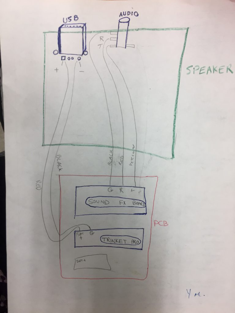
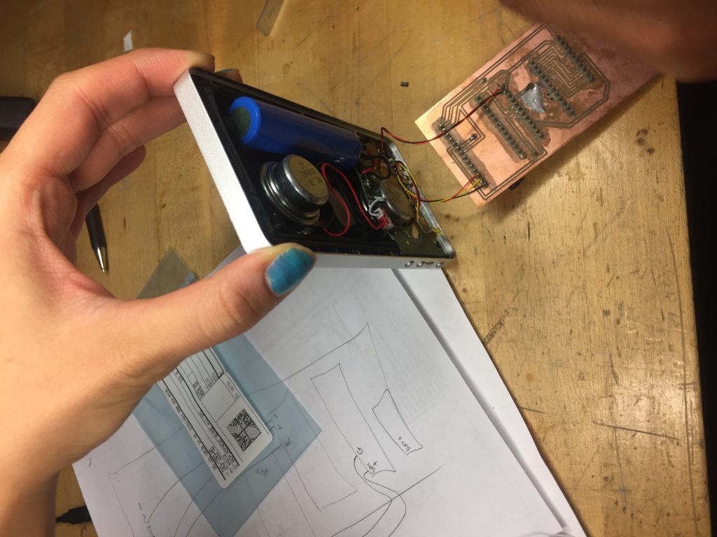
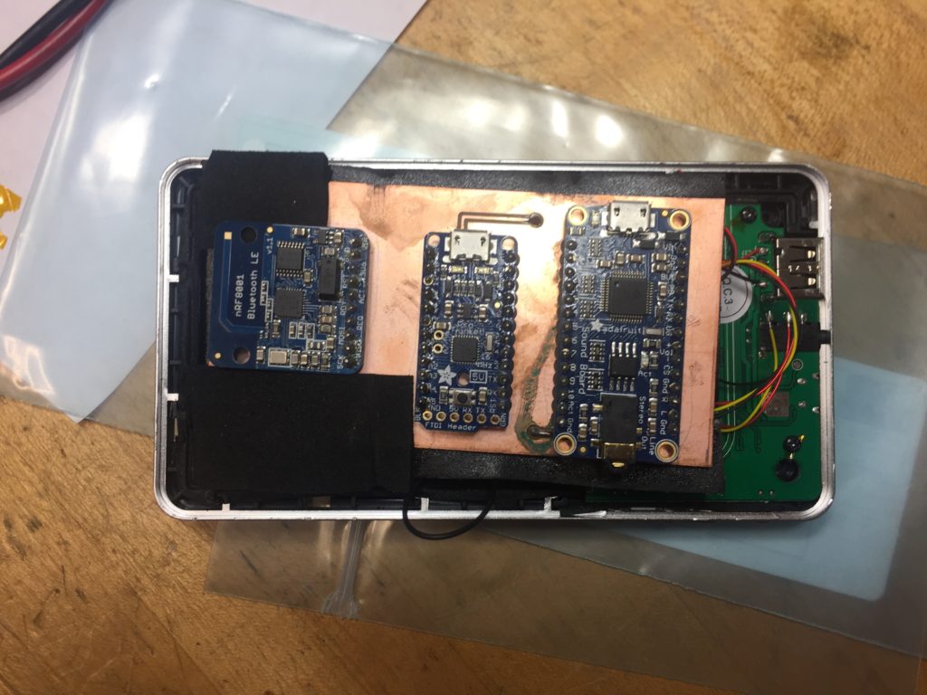
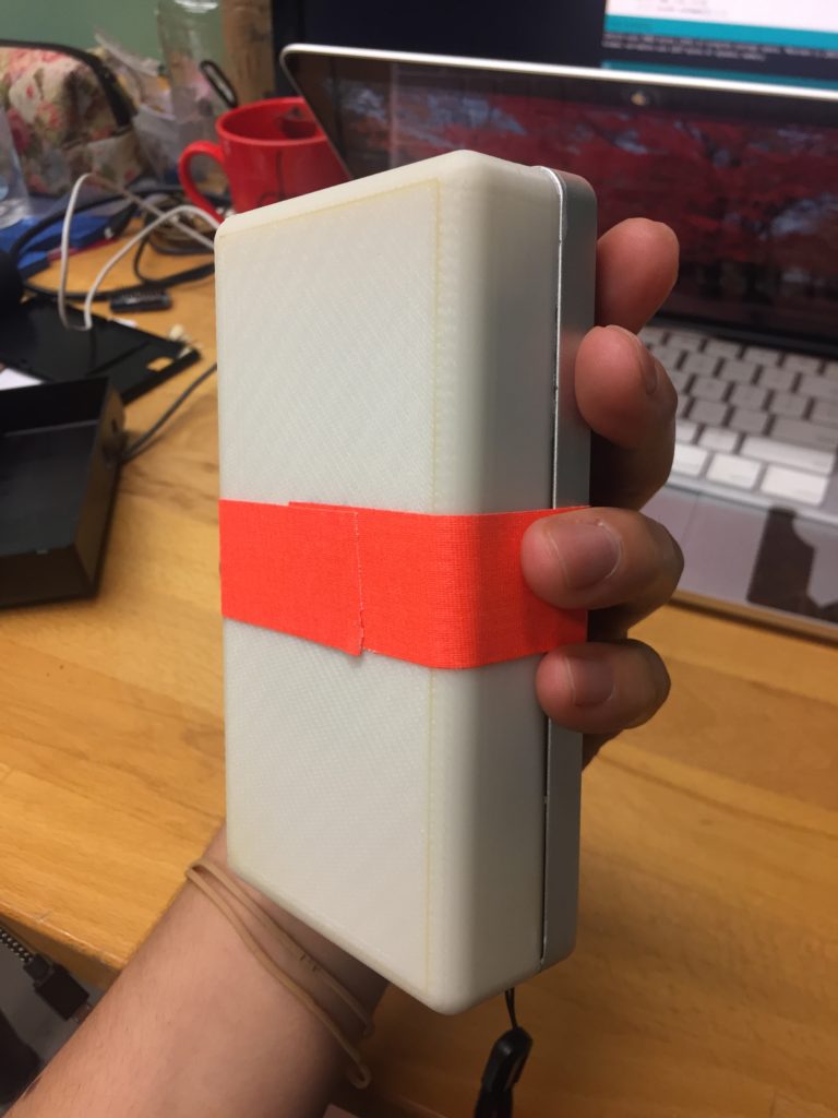
After correctly connecting the PCB board to the speaker, attach an adhesive foam to the back of the PCB and put it on top of the speaker's board. Then, place more foam on top of the PCB and put the 3D printed lid on it and press to make sure the PCB board does not move inside the case. Use super glue or tape to attach the lid to the speaker.
The pictures show the connections in real life:
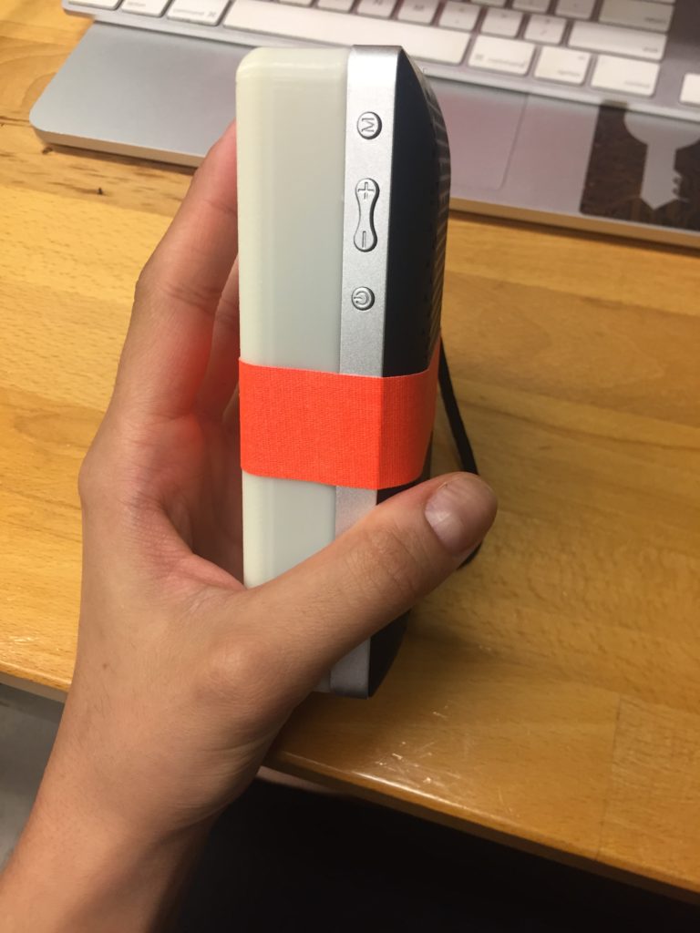
Here is the final look of the device:

Step 6: Using the device
You can find the PDF file of the SeeBox Instructions here:
https://github.com/parisa-alirezaee/SeeBoxUserManual.git
Conclusion
This video shows a demo of the final device with the phone application:
After 8 months of working hard on this design and device, we are proud and excited that we have been able to share the process with you. We hope you have enjoyed the process and we thank you for taking the time to read about what we have done. If you are planning to re-create the SeeBox, we wish you the best of luck!
Contact me with this email address if you face any difficulties in the re-creating journey:
parisa.alirezaee@mail.mcgill.ca
SeeBox Team: Ron, Pierre, Vanessa, Parisa, and Nadine